Icom 705 USB-C/SEND Board Installation Guide
Purchase your upgrade board:
Step-by-Step Guide
Tools
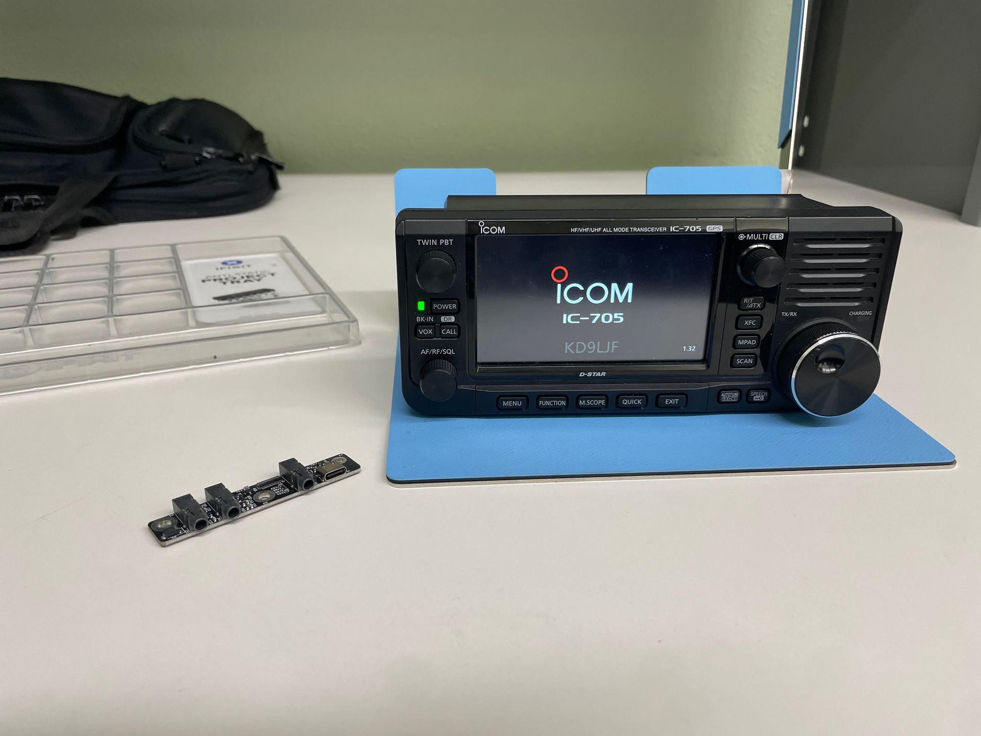
Let's get started! You will need the following:
- Your Icom 705 radio
The USB-C / SEND Upgrade Board
A quality Phillips #1 or #2 screwdriver
(Note: We’ve had reports of some customers stripping out their screws. We recommend using correct size Phillips drivers for the best results.)
- Optionally, you may want a USB-C cable and a 3.5mm headphone jack for alignment and testing.
Removal
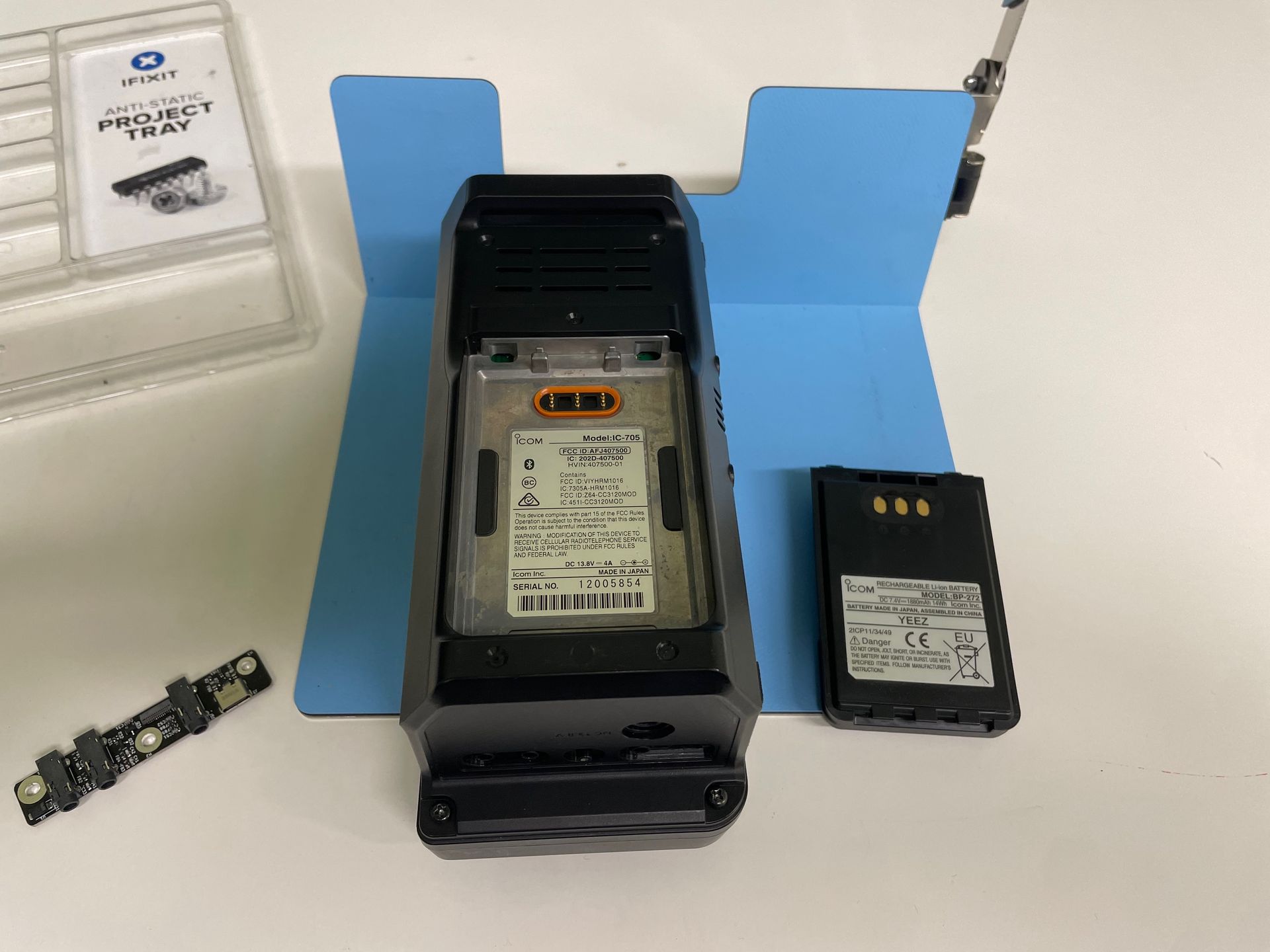
Start by making sure that the radio is powered off, power is disconnected, and the battery is removed.
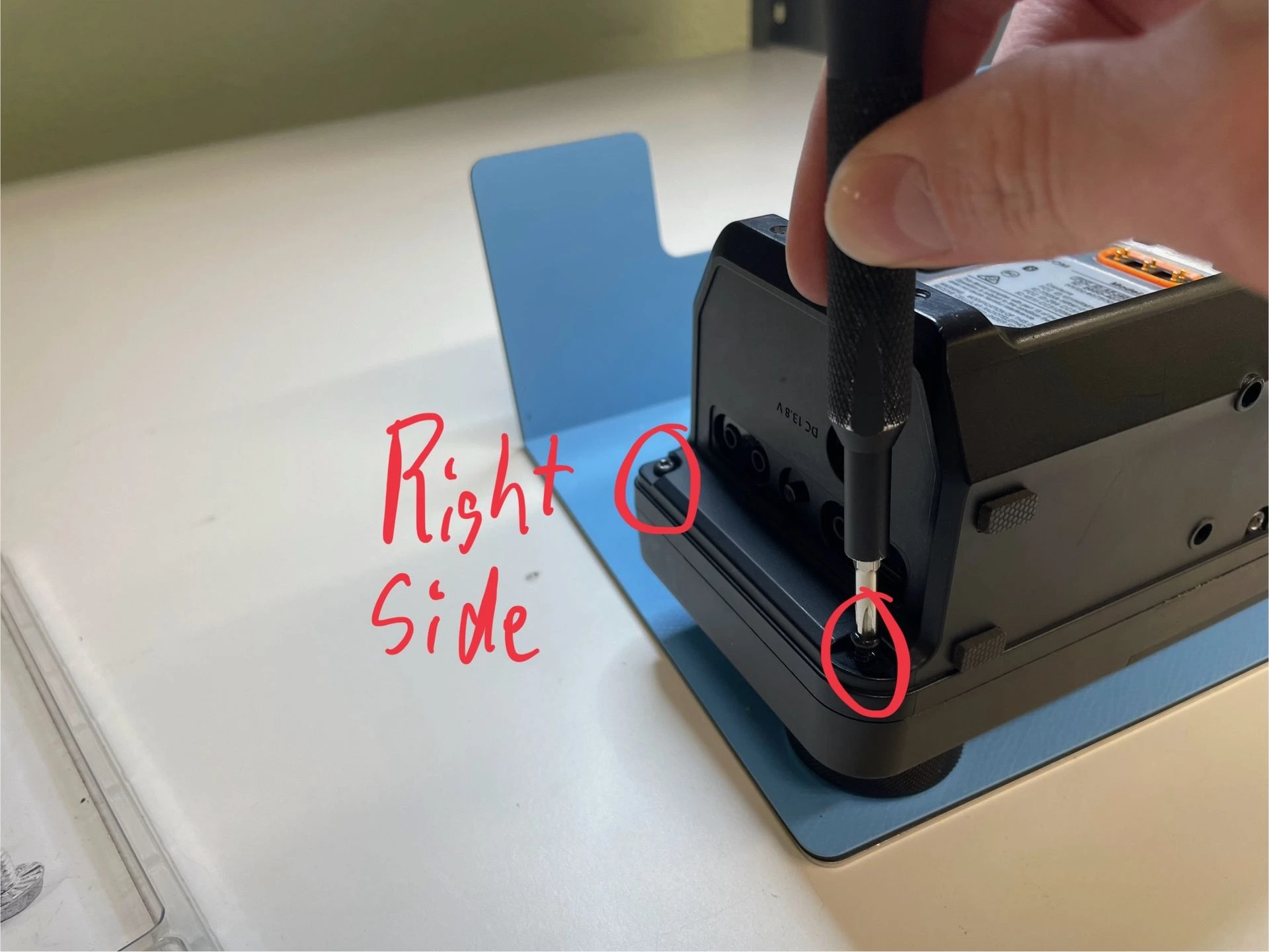
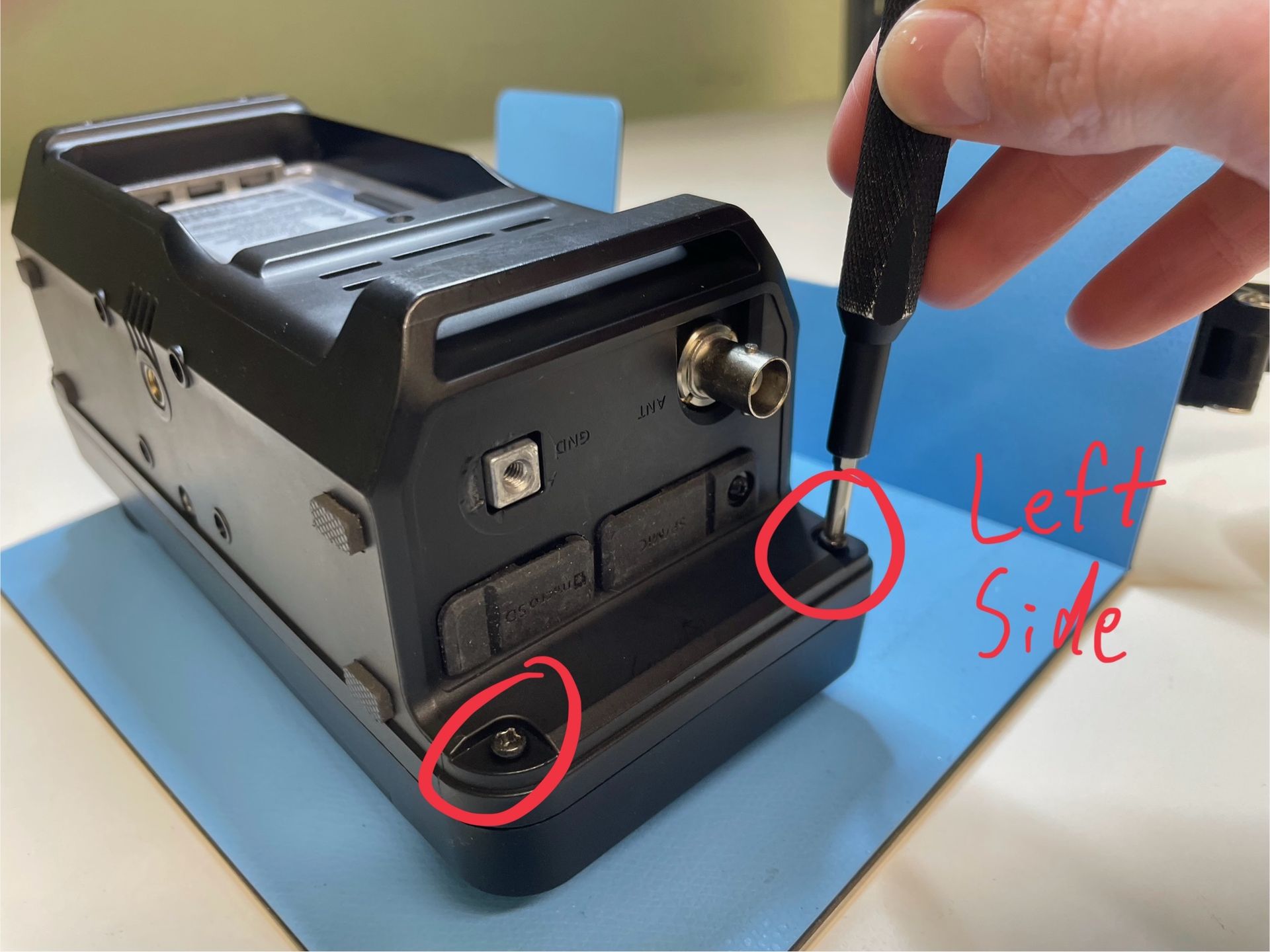
Remove the four longer screws (M3 x 12mm) from the corners of the rear housing; two on each side.
(Note: The screws are held in with Blue Loctite and may be difficult to remove the first time. Use caution to not strip out the screws.)
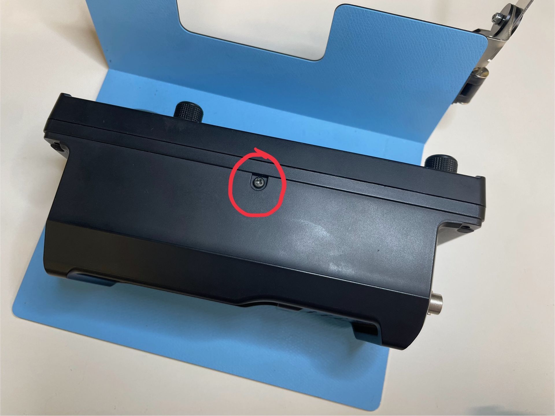
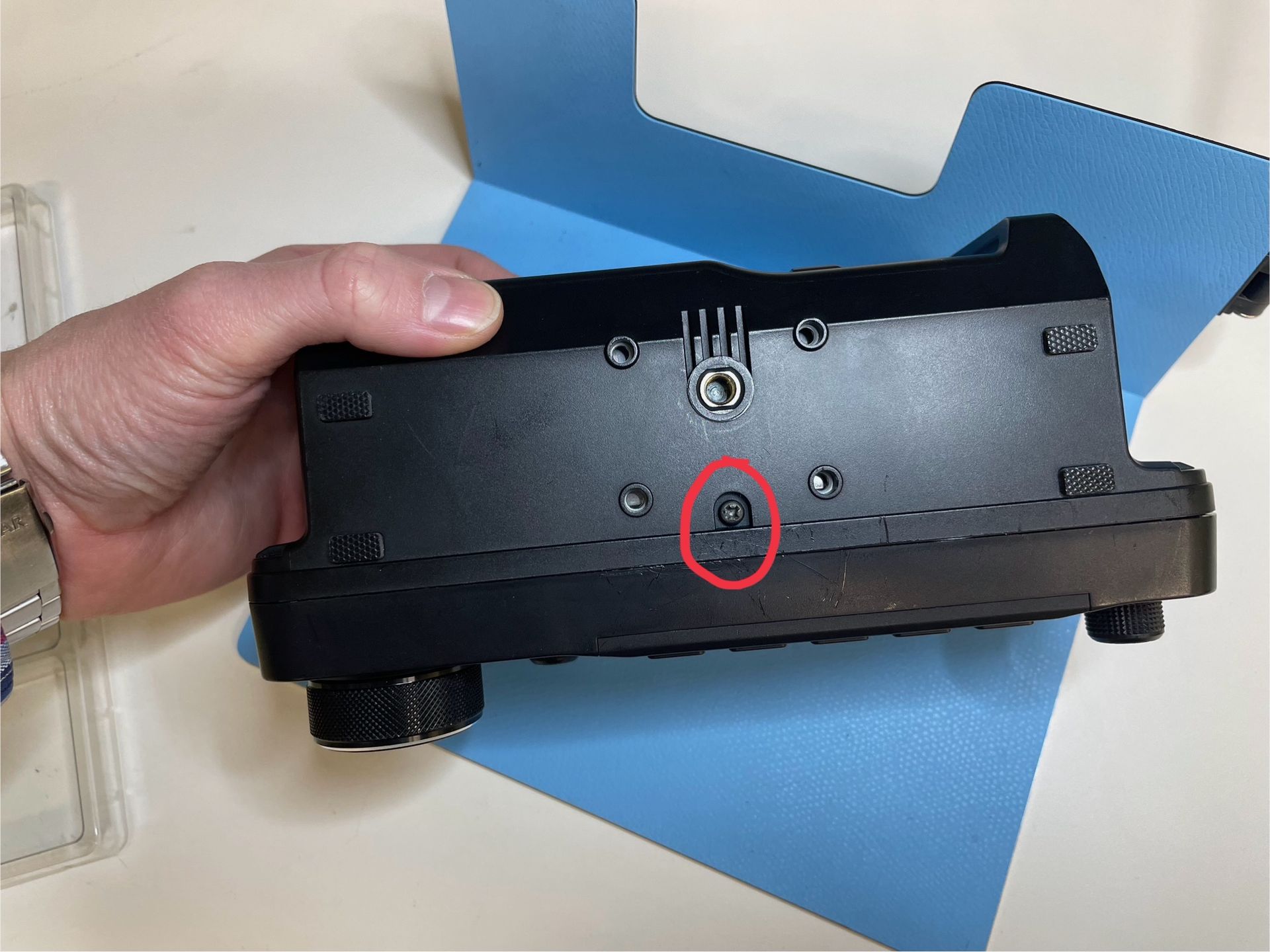
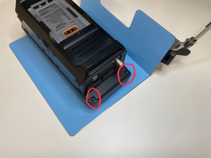
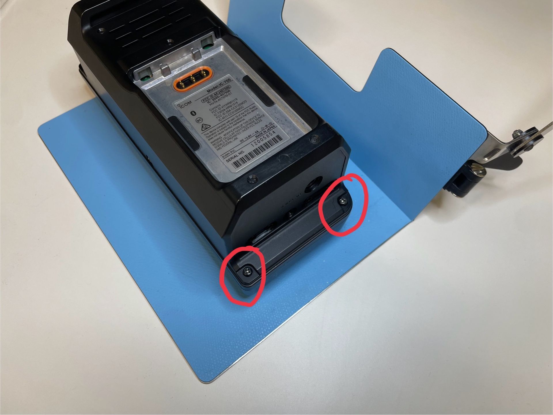
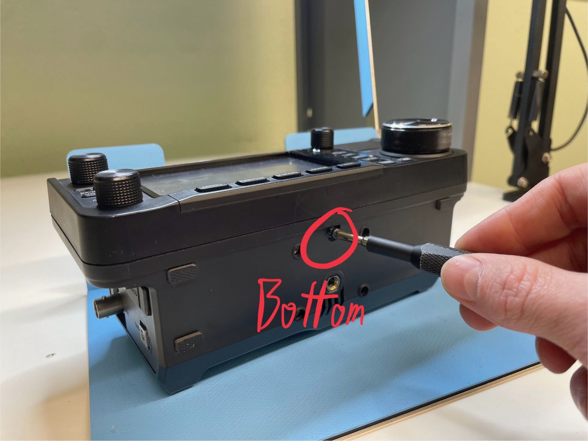
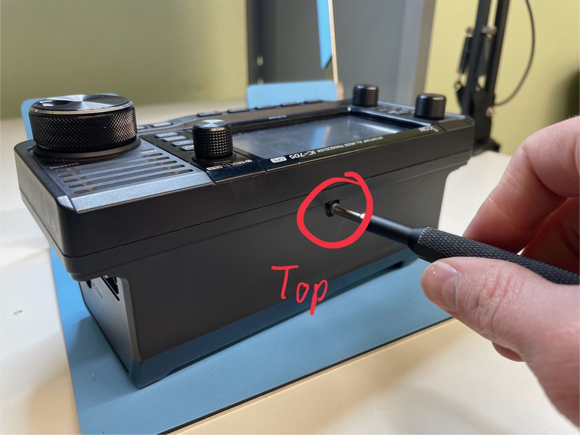
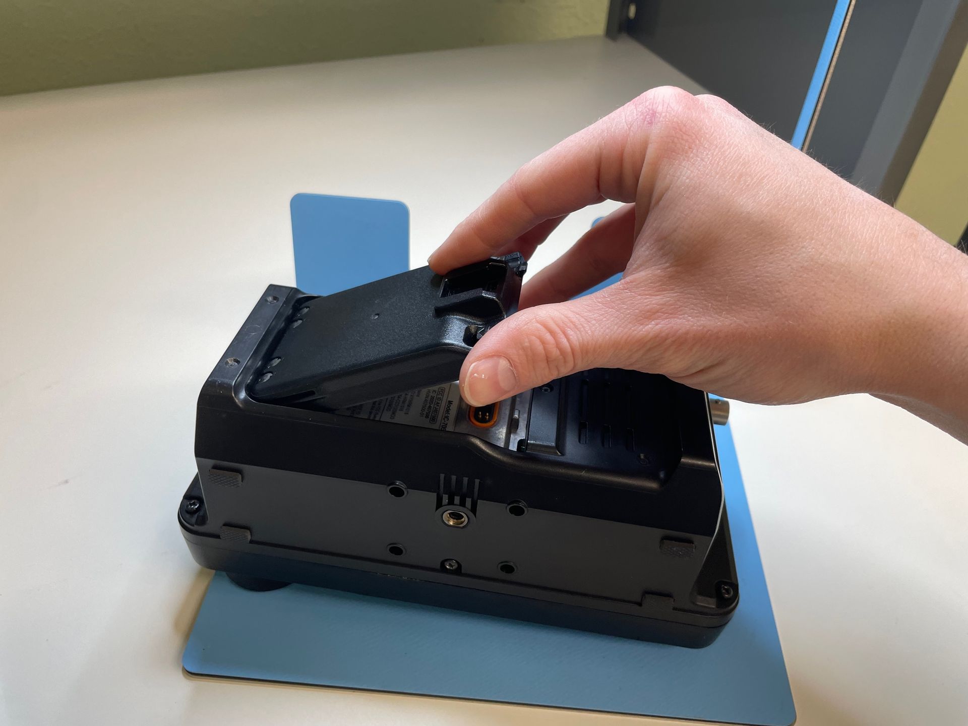
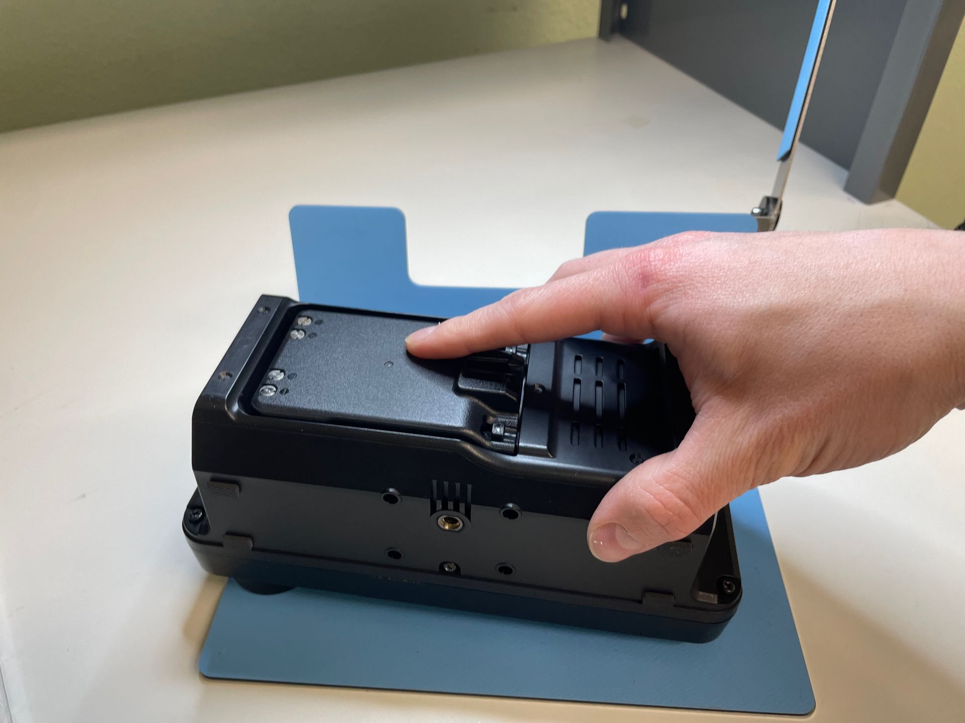
Remove the two shorter screws (M3 x 6mm) from the top and bottom of the radio. DO NOT HOLD THE RADIO BY THE DISPLAY UNIT WHILE REMOVING THE FINAL SCREWS! These are the last two screws securing the display to the main housing, and holding the radio by the display could risk ripping the ribbon cables that connect the display to the main unit.
(Note: The screws are held in with Blue Loctite and may be difficult to remove the first time. Use caution to not strip out the screws.)
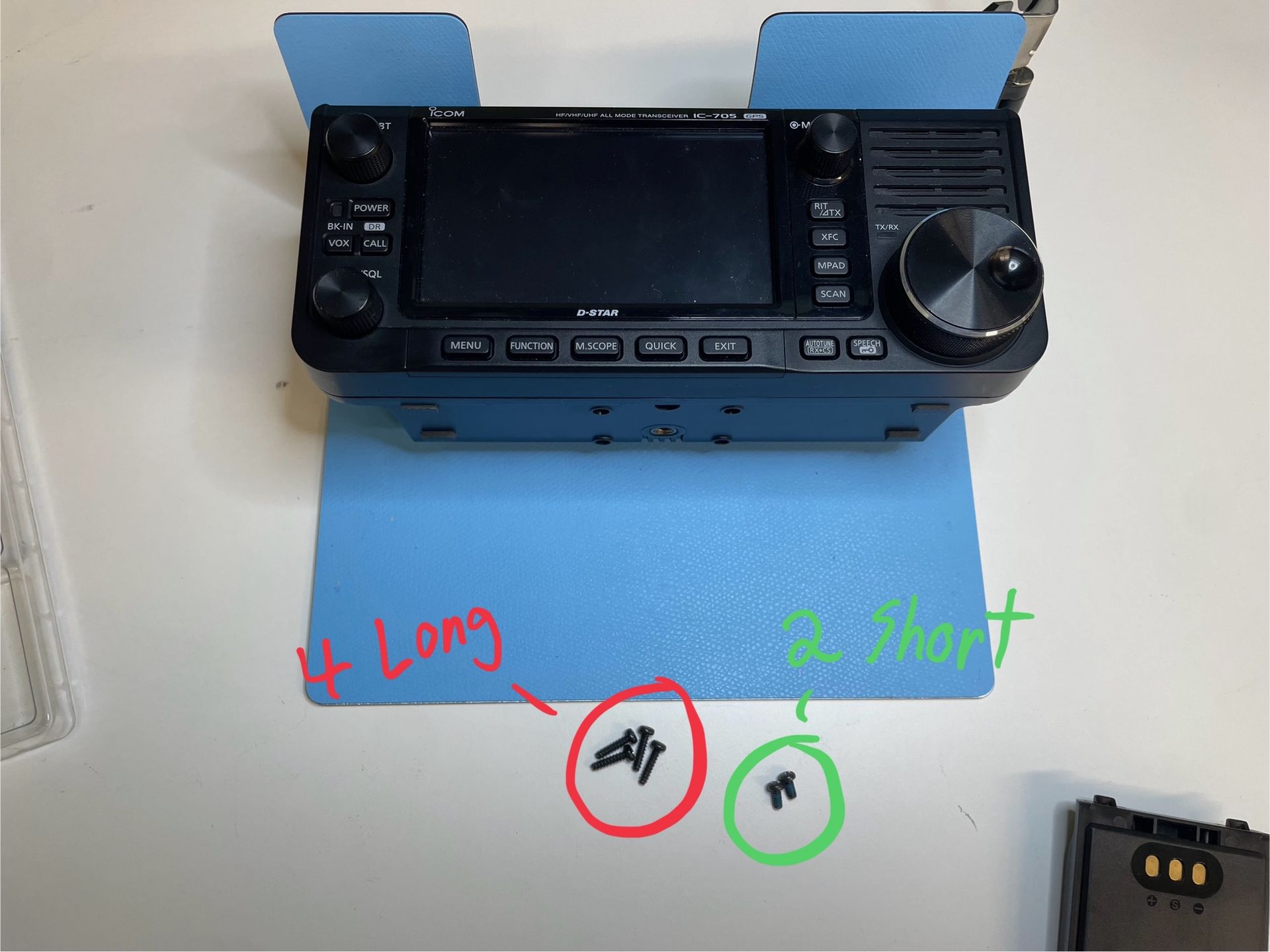
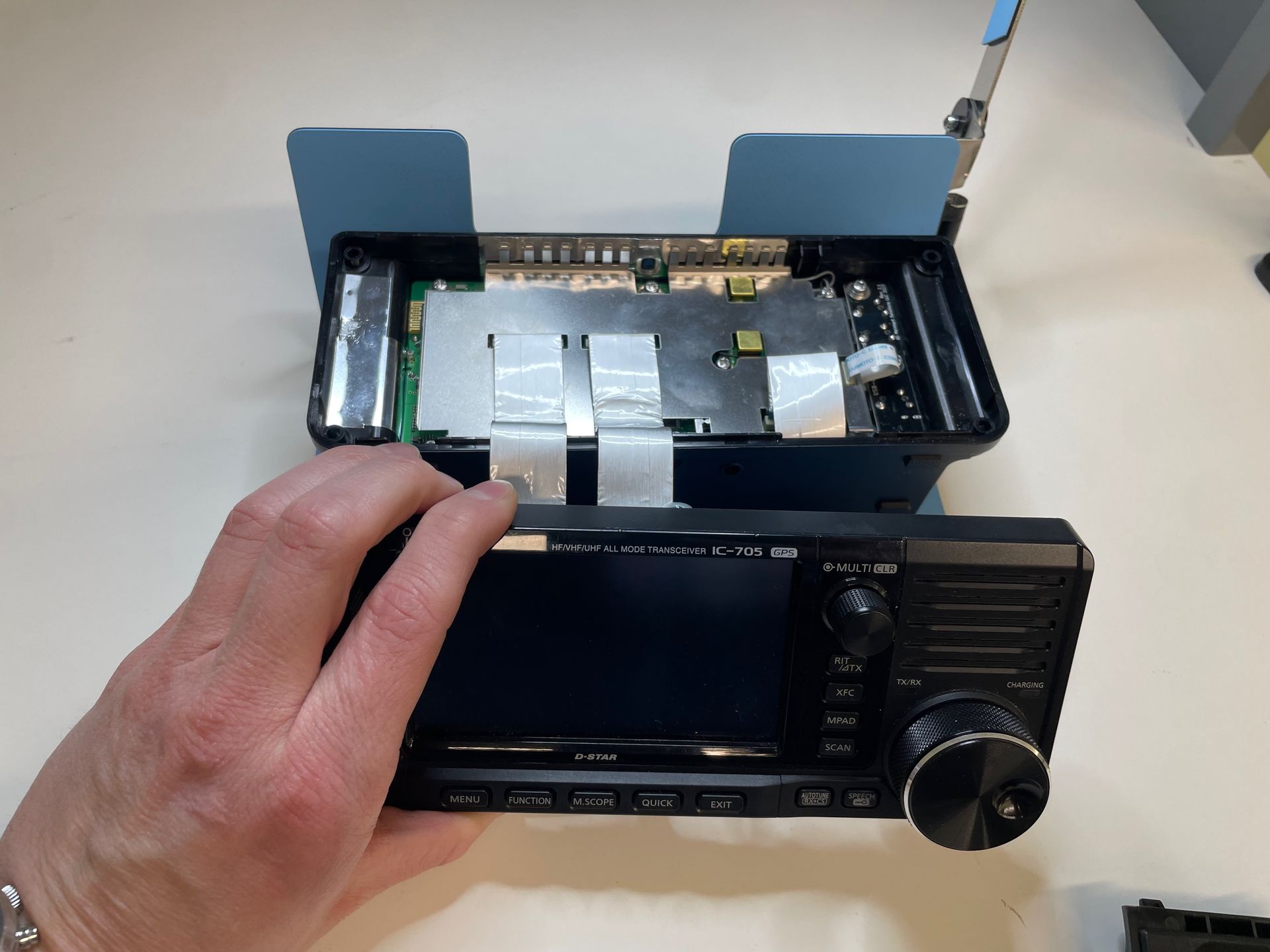
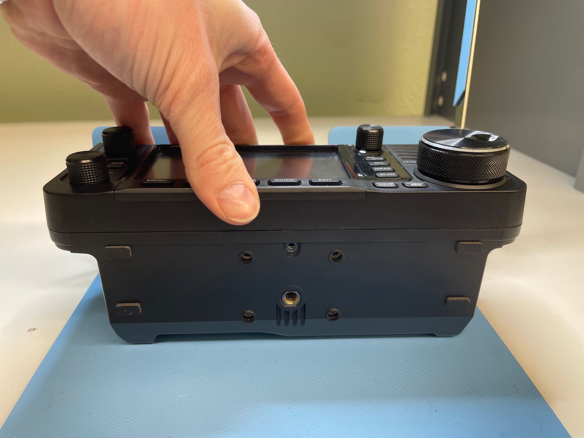
There should now be four long and two short screws removed from the radio. At this point, the display unit is free from the body of the radio. Carefully set the radio on its back with the display facing up. Orient the radio so that the menu, function, etc buttons are closest to you.
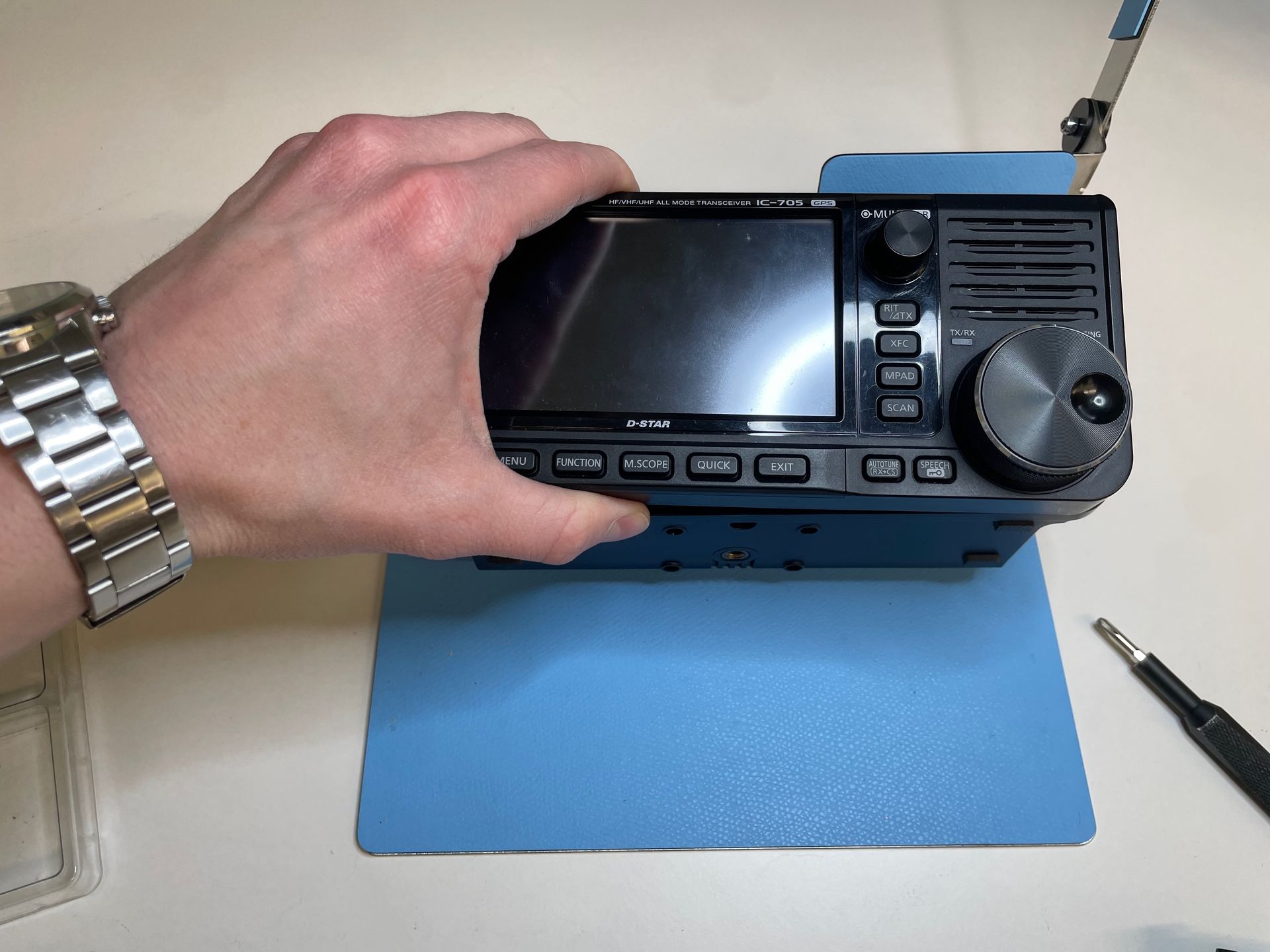
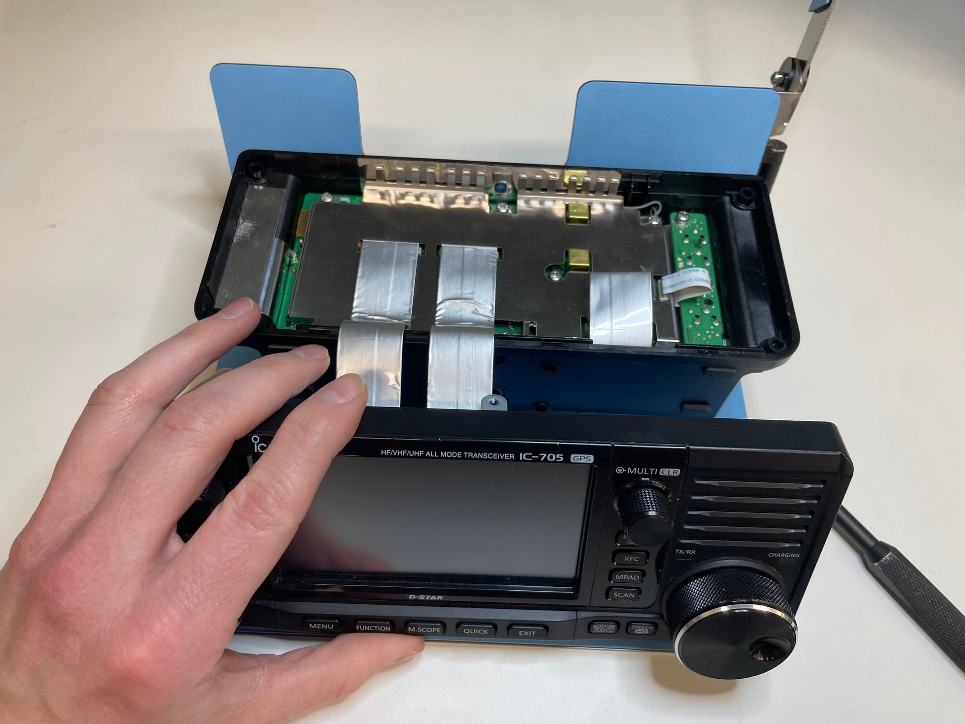
Carefully lift the display unit up from the main housing and bring it forward towards you. There are two larger ribbon cables that connect the display to the main unit. You can leave them connected and let the display balance against the cables and the side of the radio. Just be careful not to bump the display or the radio or else you could damage the ribbon cables.
If you do not feel comfortable working with the display unit attached, you can disconnect the display from the main unit by pulling the cables straight up from the main unit. There are no locking mechanisms on this connector; it is just a friction fit. During reassembly, just push straight down to seat the cable back into the connector. I personally recommend just leaving the display connected as long as you have a safe working area. This reduces the chance of damaging the cable or the connector.
We do sell replacement ribbon cables if you happen tear the cable.
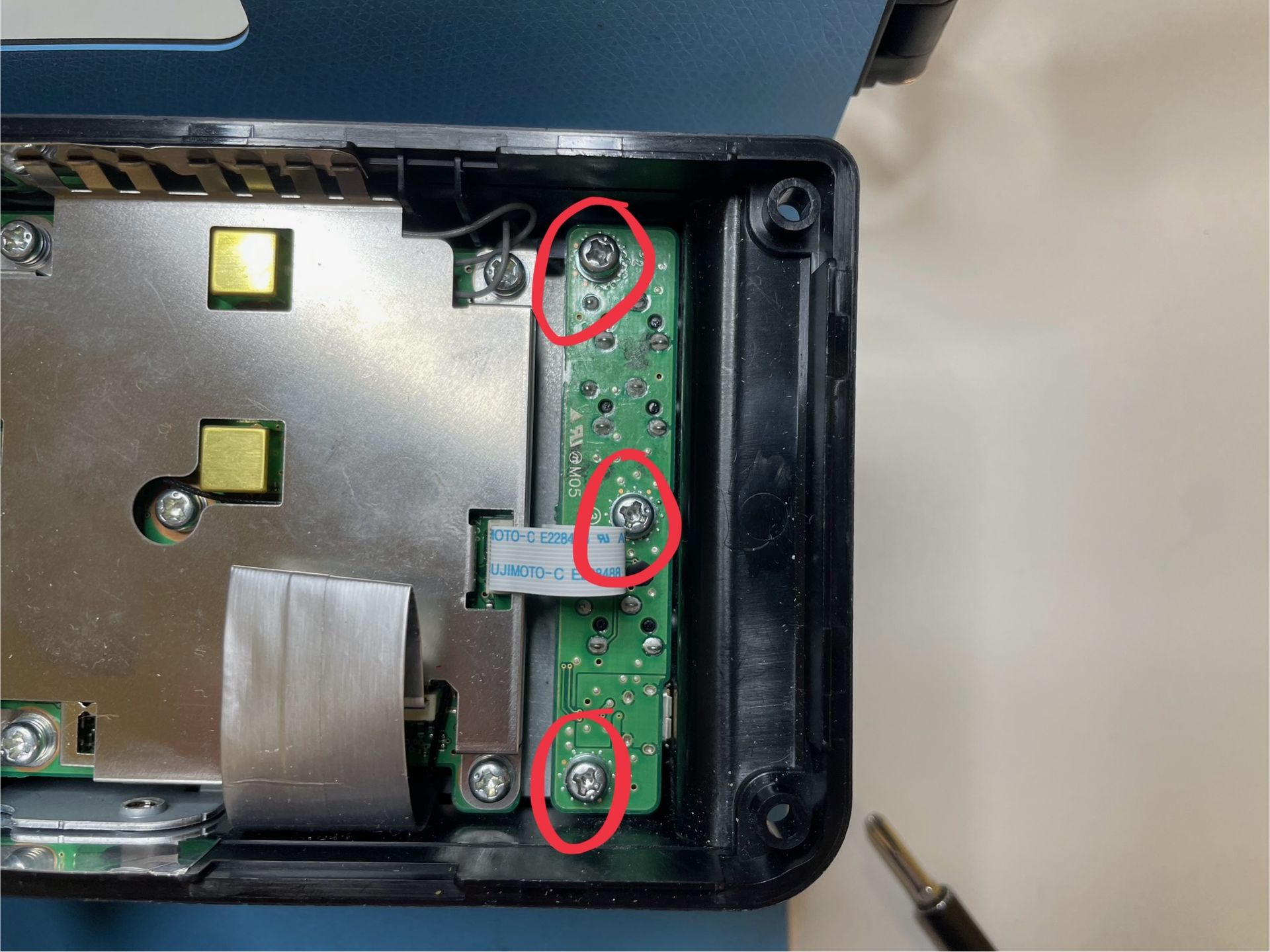
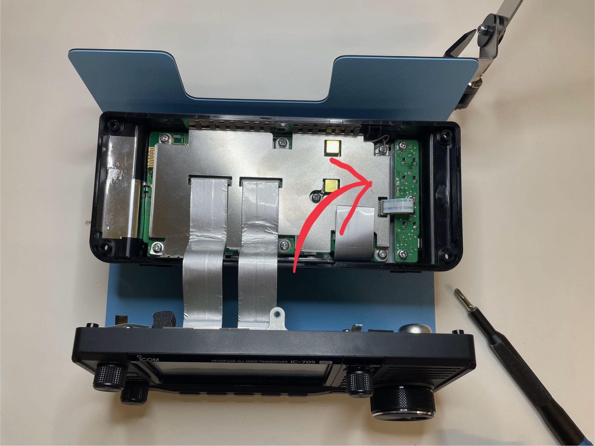
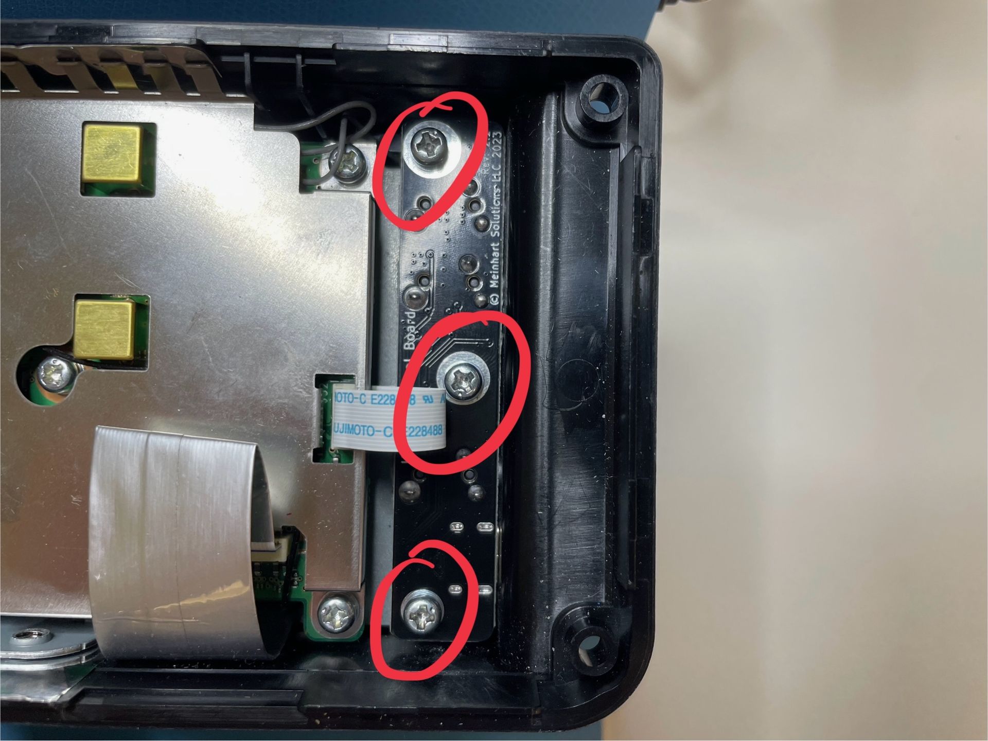
Remove the three silver screws with washers securing the control board.
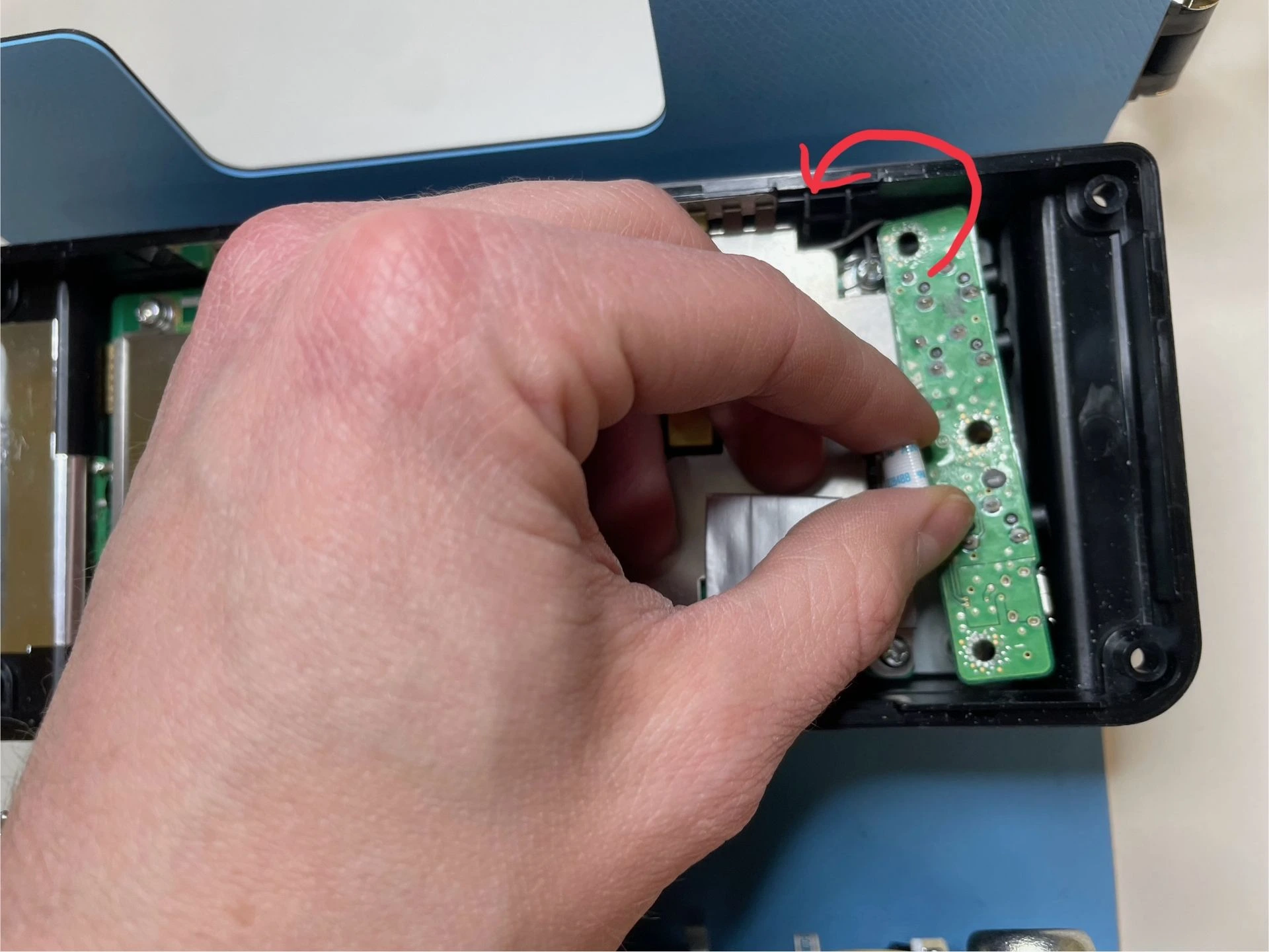
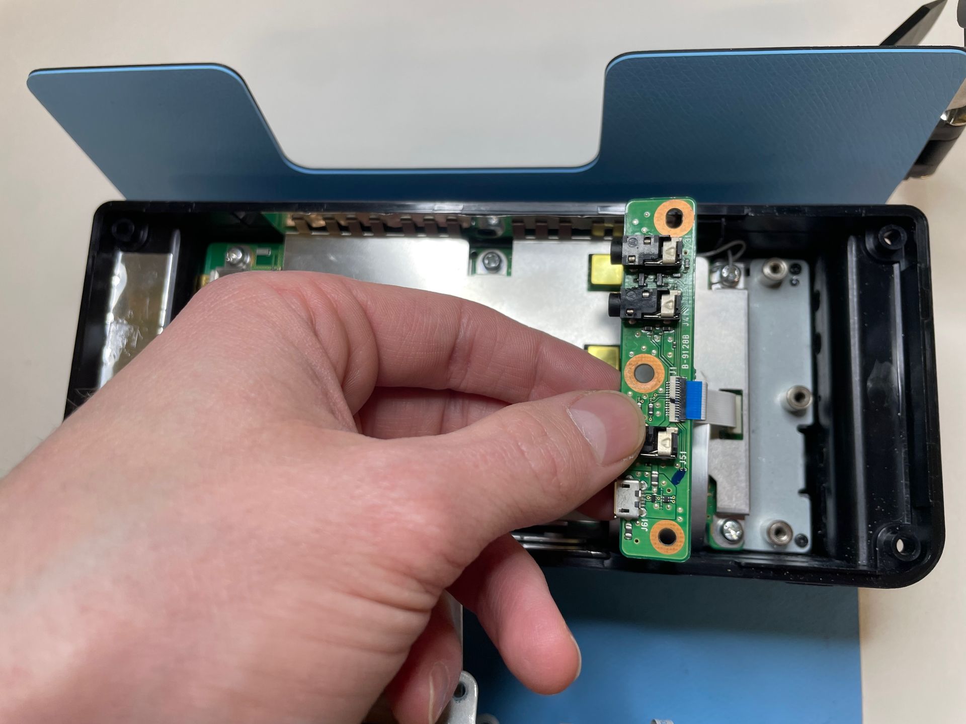
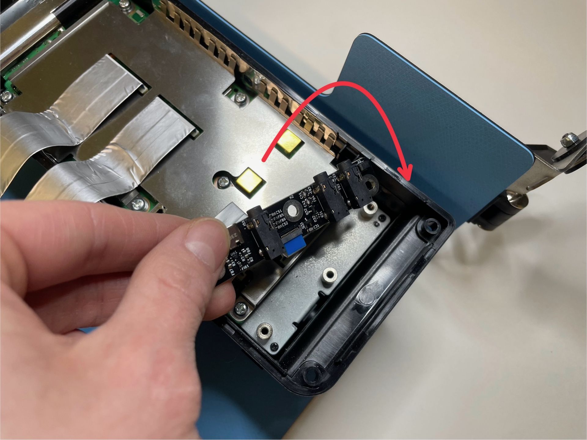
Gently pull the connect board from the housing of the radio by the flex cable. You can also use a plastic pry tool to assist in removing the board from its slot. Flip it 180º to expose the connector.
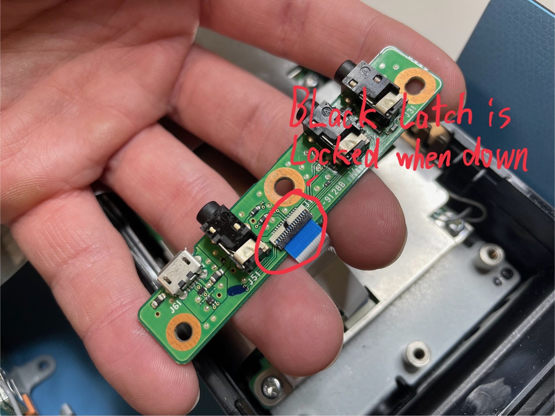
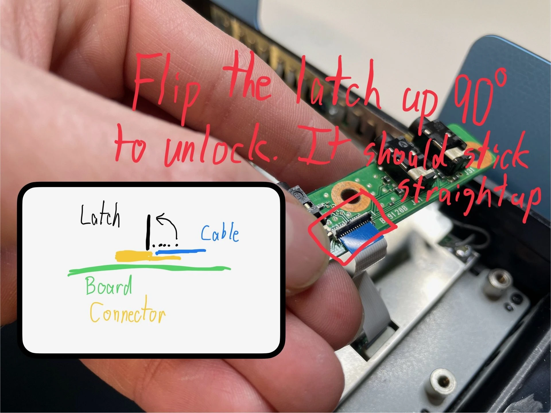
The black latch should be locked and in the down position. To unlock it, use your fingernail or a plastic pry tool to open it up 90º. Do not go past 90º or use excessive force; otherwise, you can easily damage the latch. (See the second photo above for the diagram.)
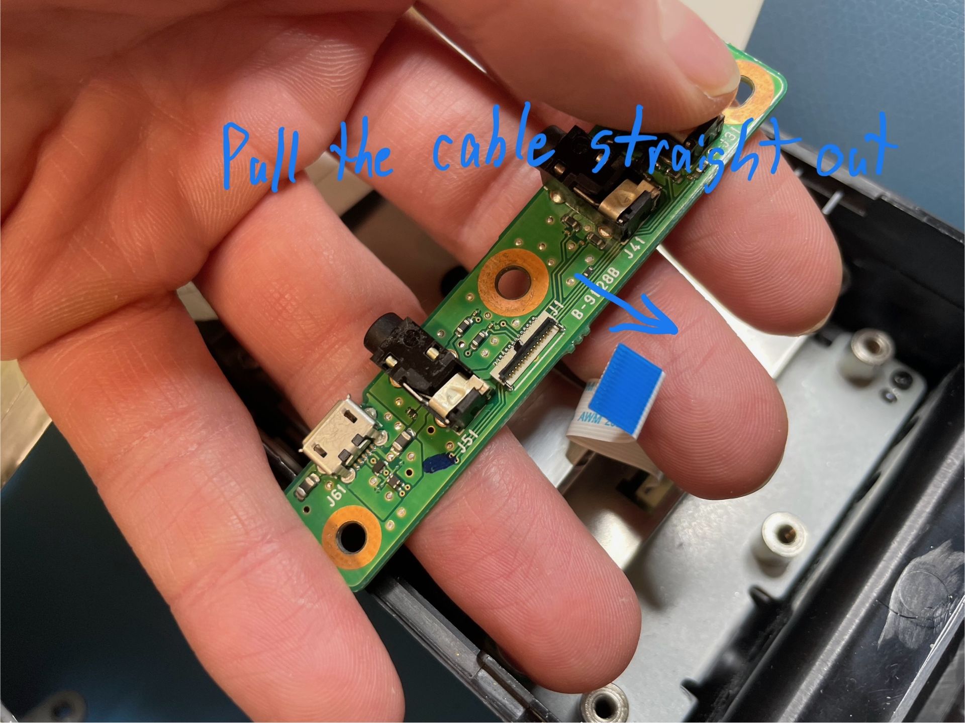
Once the latch is opened, pull the cable away from the board.
Now that this step is complete, you are already halfway through the swap! Give yourself a pat on the back. 😀👍
Onto installing the replacement board…
Reassembly
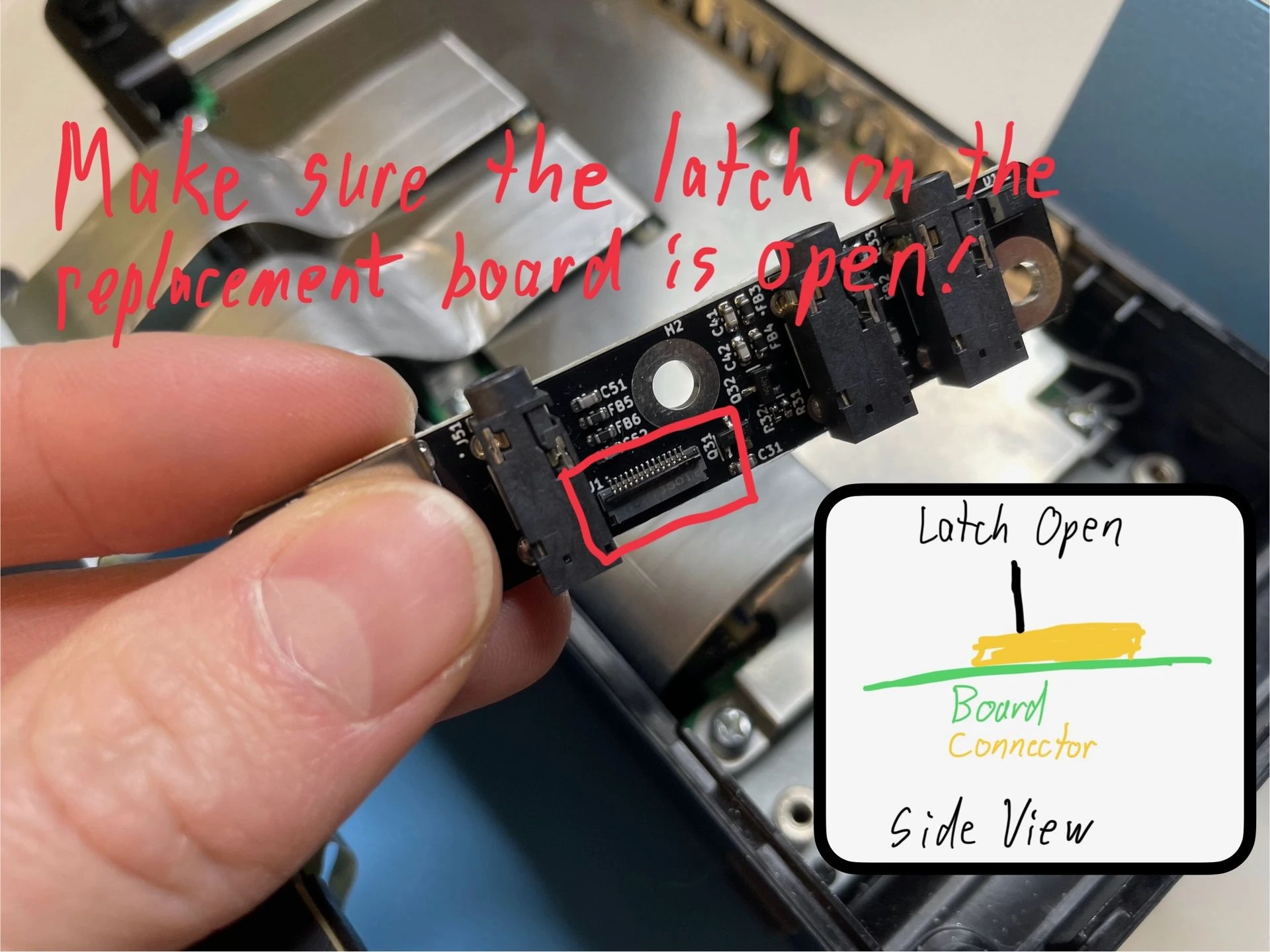
Check that the latch on the upgrade board is up. The connector on the replacement board is a bit different from the stock board, but it is still unlocked when the latch is up.
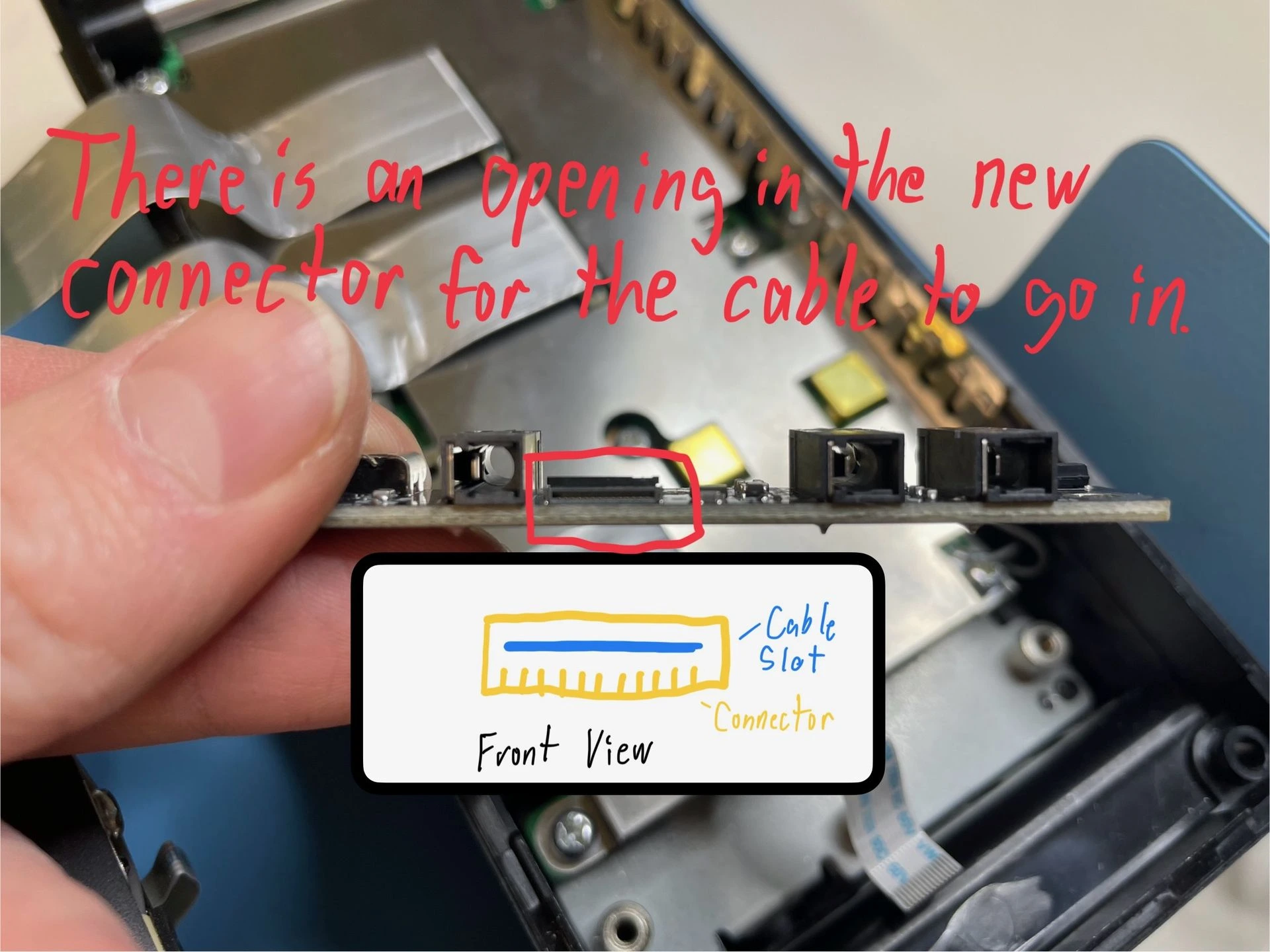
The cable will be in the same orientation in the new board’s connector as it was on the old board. However, the new connector has a more defined slot for the cable to go into. See the photo above and inspect the difference between the old and the new board for yourself.
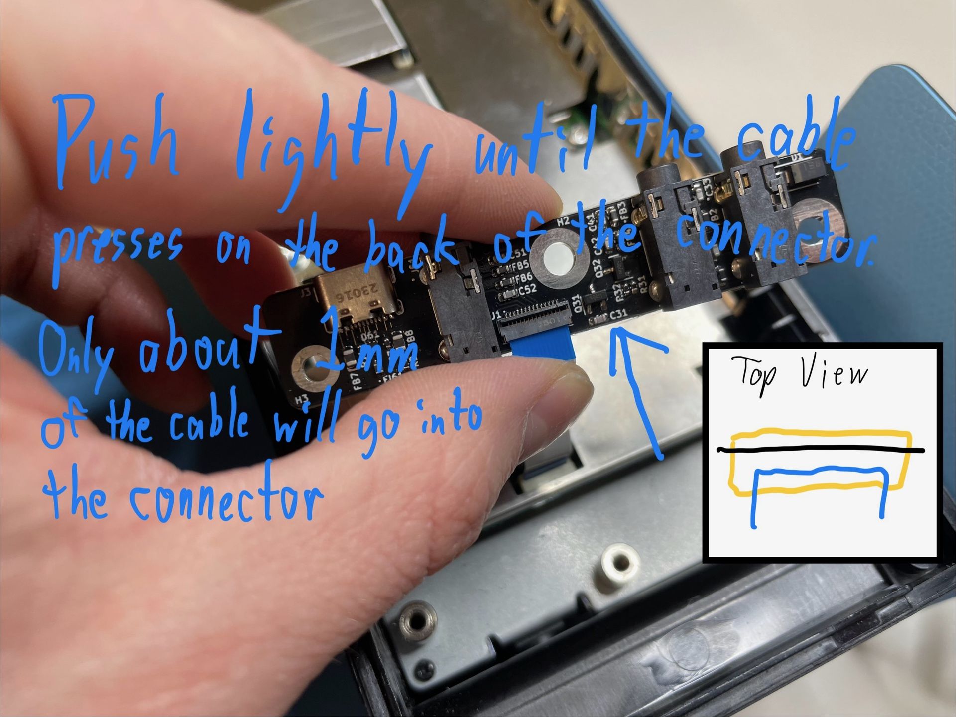
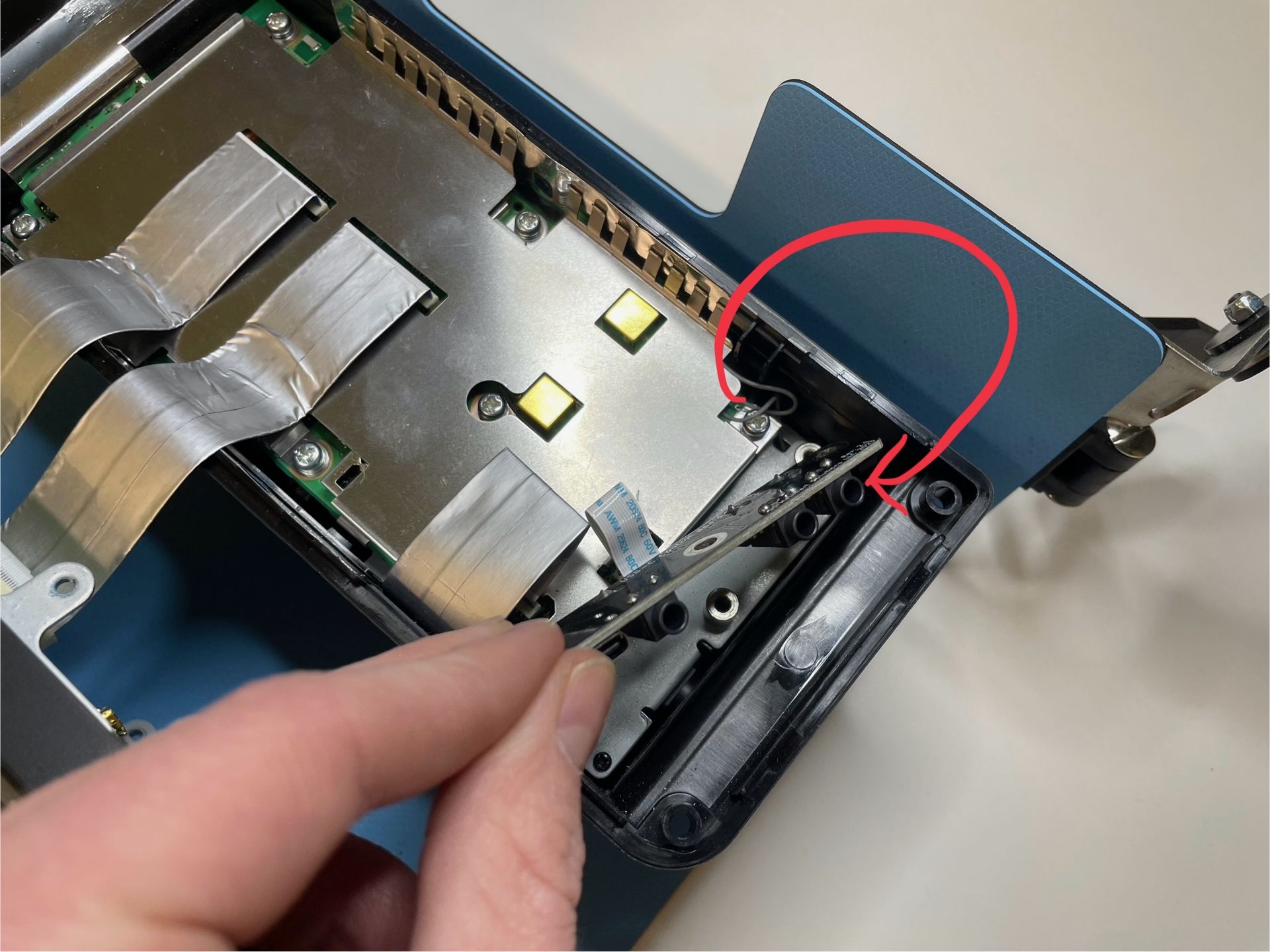
To install the new board, insert the cable into the connector as shown above. Gently push the cable until you feel it hit the back of the connector. It will not go into the connector very far, only about 1mm. The diagram in the photo is a top-down view of the cable outlined in blue going into the connector outlined in yellow. The latch is in black as a reference.
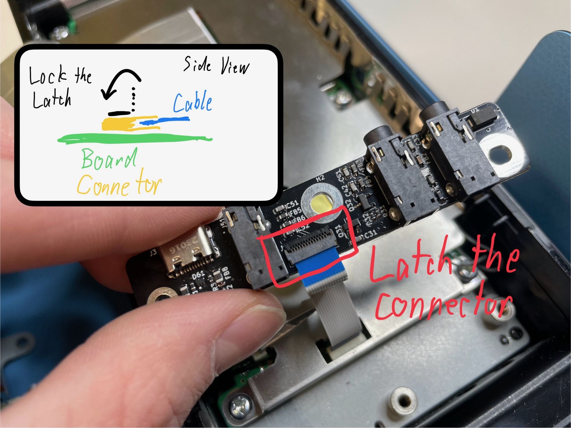
To lock the cable in place, carefully push the black latch away from the cable. This differs from the stock board, where the latch locks towards the cable. Ensure that the cable is still seated correctly in the connector when you lock the latch. The latch is locked when it is flat with the rest of the connector. (See the diagram above.)
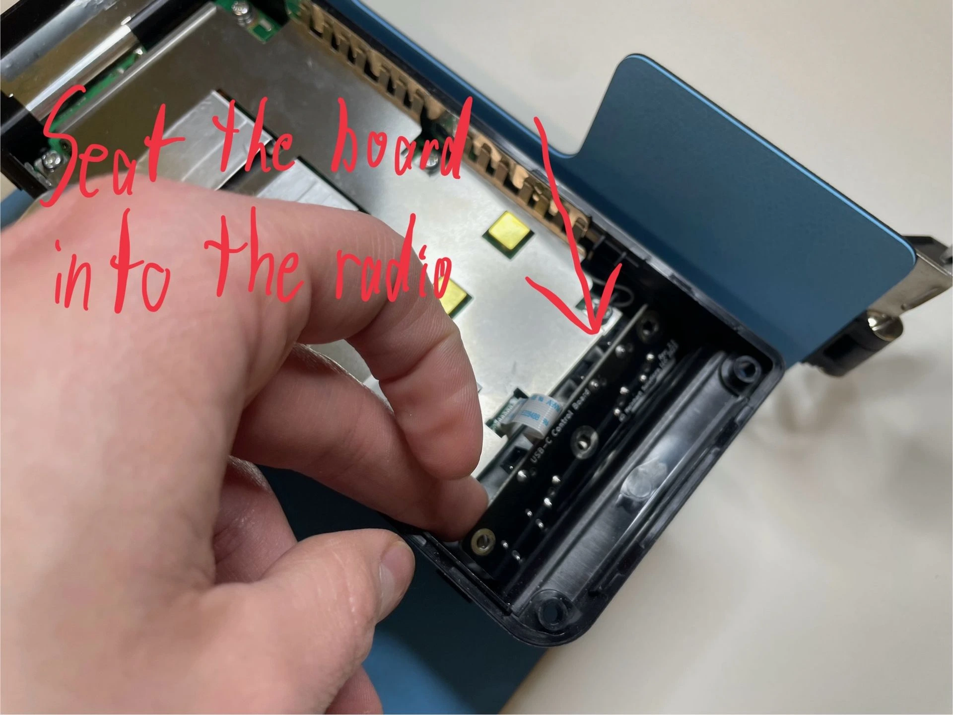
Now that the cable is locked into the connector on the new board, flip the board over and seat it into the housing.
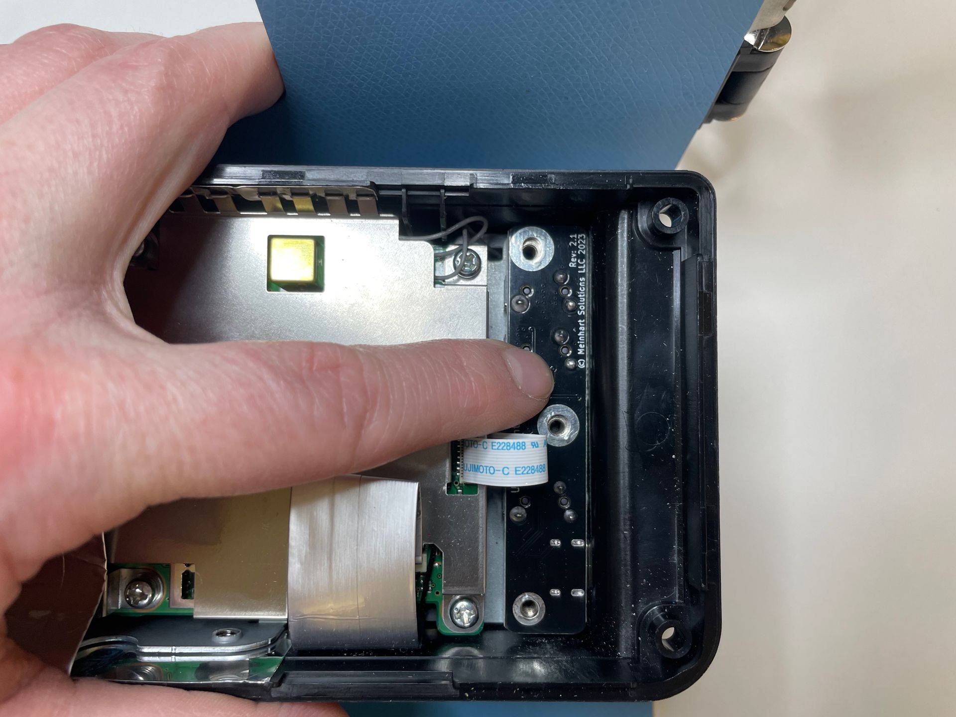
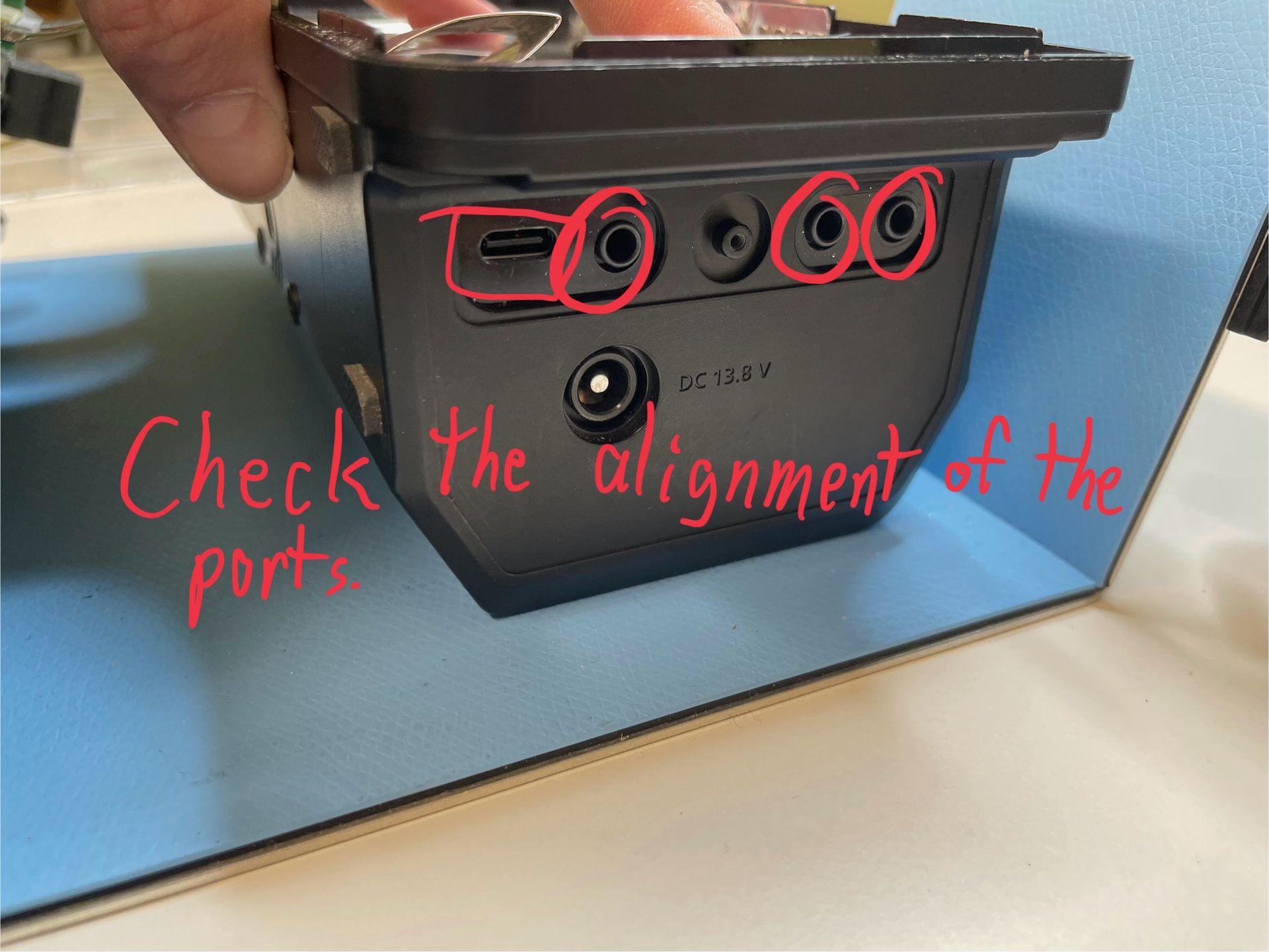
Carefully push down on the board and maneuver it so that the ports align correctly on the side. (Note that I removed the rubber gasket covering the ports to make it easier to show, but this is not necessary.)
Reinstall the three silver screws with their lock washers. Finger tight only; do not over tighten the screws. Double check the port alignment is still good after this step.
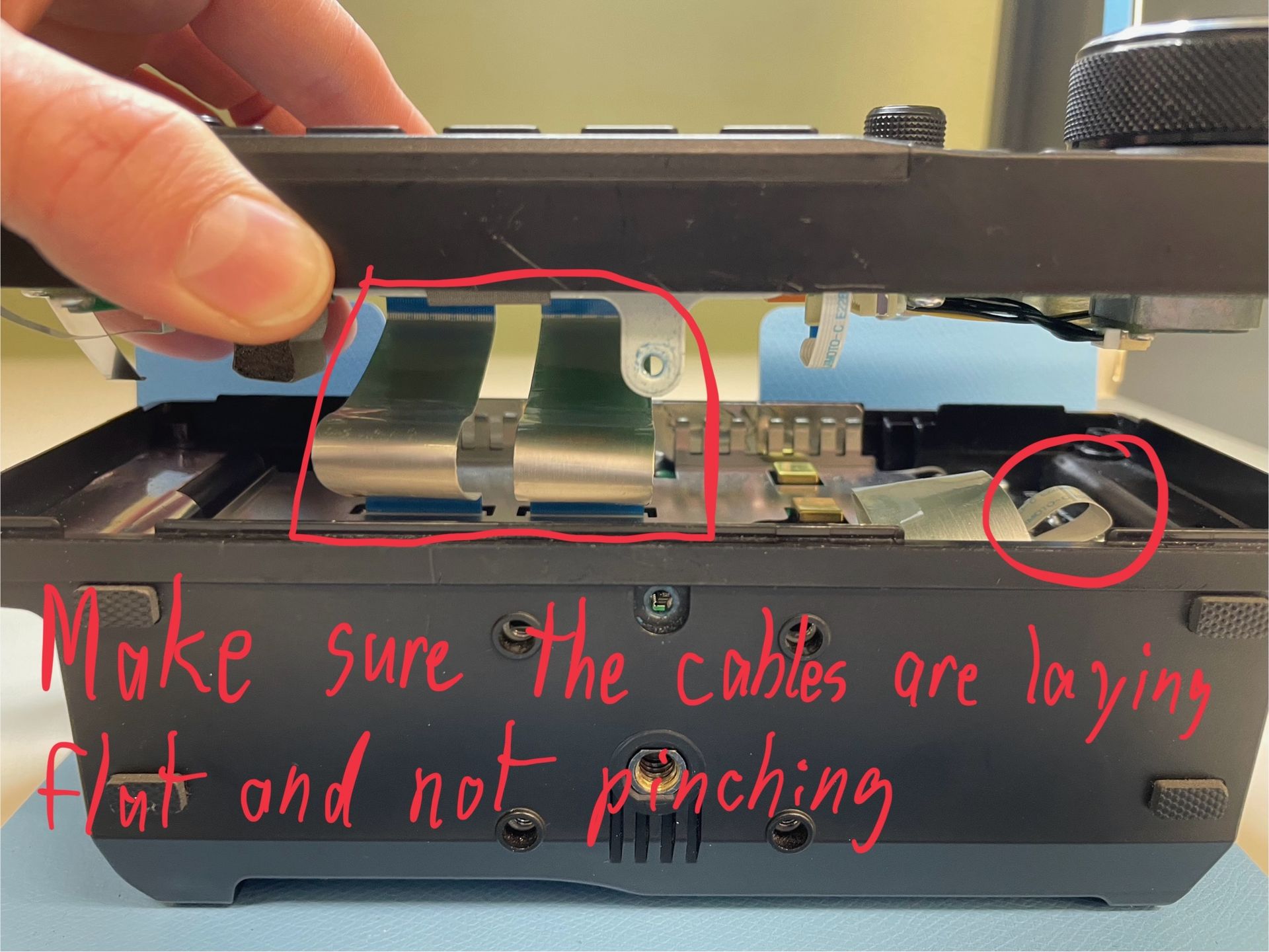
Reinstall the display unit onto the main housing. If you previously disconnected the display unit cables, reconnected them at this point. Double check your placement of the display unit so that it is going into the proper spot and not pinching any of the flex cables.
Reinstall the two shorter Phillips screws on the top and bottom along with the four longer screws in the four corners.
All done! Reinstall your battery and turn on your radio. Test out your USB-C port and the other connectors to ensure it is working before you return to the field.
Check to make sure that your radio does not start transmitting immediately when you turn it on. If it does, the ribbon cable connecting the new control board is likely not seated properly. Try reconnecting it and testing it again. If the issue persists, or you have any other questions, please contact radio@ihelpu.tech.
I hope you enjoyed the installation and the upgrade board serves you well! Don’t hesitate to reach out if you have any questions.
73’s
Ben Meinhart, KD9LJF